Unveiling The Superheterodyne Block Diagram: Radio's Masterpiece
In the realm of radio communication, few inventions have had as profound and lasting an impact as the superheterodyne receiver. This ingenious architecture, developed in the early 20th century, revolutionized how we listen to the world, offering a vast improvement over the simpler, less efficient tuned radio receivers that came before it. Understanding the core of this innovation means diving into the intricate yet elegant structure of the superheterodyne block diagram.
From tuning into your favorite FM station to enabling complex wireless systems, the principles behind the superheterodyne receiver circuit remain a fundamental building block of modern communication. This article will demystify this essential technology, guiding you through each component of its block diagram and explaining how they work in harmony to deliver clear, sensitive, and selective radio reception.
Table of Contents
- The Dawn of Modern Radio: Understanding the Superheterodyne Receiver
- Decoding the Superheterodyne Block Diagram: An Overview
- Key Components of the Superheterodyne Receiver
- The Antenna: Gateway to the Airwaves
- RF Amplifier: The First Stage of Signal Conditioning
- The Mixer: Where Frequencies Converge
- The Local Oscillator (LO): The Heartbeat of Frequency Conversion
- IF Amplifier: The Workhorse of Gain and Selectivity
- The Detector/Demodulator: Unveiling the Information
- AF Amplifier and Speaker: Bringing Sound to Life
- The Critical Role of Image Frequency Rejection
- Enhancing Performance: Sensitivity and Selectivity
- Operation and Alignment: Bringing the Superhet to Life
- Beyond Reception: Superheterodyne in Transmitters
- The Enduring Legacy of Superheterodyne Technology
The Dawn of Modern Radio: Understanding the Superheterodyne Receiver
The superheterodyne receiver, often affectionately shortened to "superhet," stands as a monumental achievement in electrical engineering. Its invention marked a pivotal moment, transforming radio from a quirky, often unreliable curiosity into a robust, high-performance communication tool. Before the superhet, simple tuned radio receivers struggled with poor selectivity and sensitivity, making it difficult to pick out a weak station from a cacophony of others or to receive distant signals clearly. This innovative architecture fundamentally changed the game. It introduced the concept of converting incoming radio frequency (RF) signals to a fixed, lower intermediate frequency (IF), where amplification and filtering could be performed much more effectively. This ingenious approach allowed for the reception of a wide range of frequencies with high sensitivity and precision, making the superheterodyne receiver circuit a fundamental building block of modern communication systems.Why "Superheterodyne"? Unpacking the Name
The term "superheterodyne" itself offers a clue to its operation. "Heterodyne" refers to the process of mixing two frequencies to produce new frequencies, specifically their sum and difference. The "super" prefix, in this context, alludes to "supersonic" or "above audible frequencies." The core reason this architecture is called a superheterodyne receiver architecture is because it involves mixing the incoming radio frequency (RF) signal with a locally generated signal (from the Local Oscillator) to create a new, lower, fixed frequency – the Intermediate Frequency (IF). This IF is typically higher than the audio frequencies but lower than the original RF, hence the "super" or "supersonic" aspect in its original context. This frequency conversion is the heart of the superhet's brilliance, enabling superior performance.Decoding the Superheterodyne Block Diagram: An Overview
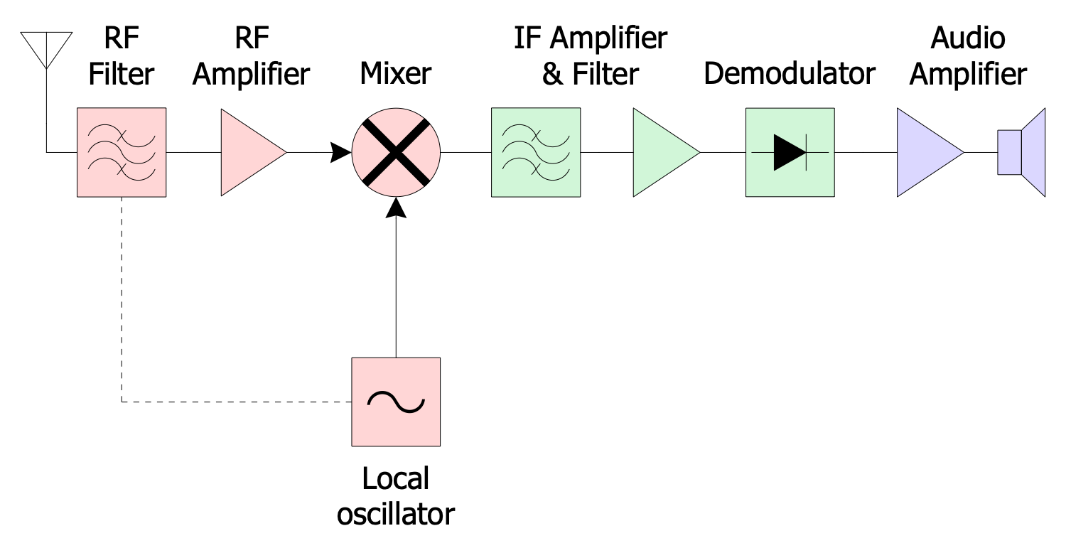
At its heart, a superheterodyne receiver usually consists of an antenna, RF amplifier, mixer, local oscillator, IF amplifier, detector, AF amplifier, and a speaker. This sequence of blocks represents a sophisticated signal processing chain designed to capture, isolate, amplify, and finally convert radio waves into audible sound or data. The working of a superheterodyne receiver is a testament to clever engineering, transforming a weak, high-frequency signal into a clear, usable output. The below figure, conceptually, shows the superheterodyne receiver block diagram, illustrating the flow of the signal through each stage.The Core Principle: Frequency Conversion
In a superheterodyne receiver, the incoming RF signal frequency is combined with the local oscillator signal. This combination, performed by the mixer, is the cornerstone of the superhet's operation. Instead of trying to amplify and filter the high-frequency RF signal directly, which is challenging due to varying bandwidths and filter characteristics across a wide frequency range, the superhet converts it to a fixed Intermediate Frequency (IF). This fixed IF allows for highly selective and stable amplification, regardless of the original incoming frequency. This makes the superheterodyne block diagram incredibly efficient and adaptable.Key Components of the Superheterodyne Receiver
Let's explore each major block within the superheterodyne block diagram, understanding its function and contribution to the overall system. Here is a block diagram of a typical superheterodyne (superhet) radio receiver, together with theory and notes explaining each block, kept very simple and at an introductory level.The Antenna: Gateway to the Airwaves
The journey of any radio signal begins at the antenna. This is the initial point where electromagnetic waves, carrying the radio signal, are converted into electrical currents. The antenna's design is crucial for efficiently capturing these waves, and its characteristics can significantly influence the receiver's overall performance. For an FM superheterodyne receiver, the antenna is designed to be resonant or effective at the FM broadcast band frequencies.RF Amplifier: The First Stage of Signal Conditioning
Following the antenna, the incoming signal passes through the RF amplifier. In the superheterodyne receiver, the incoming signal through the antenna is filtered to reject the image frequency and then amplified by the RF amplifier. This stage has several critical roles: * **Amplification:** It boosts the very weak signal received by the antenna to a more usable level, improving the receiver's sensitivity. The gain of the RF amplifier is one of the factors determining the sensitivity of the superheterodyne receiver. * **Selectivity:** The RF amplifier can be tuned to select a specific band of frequencies, helping to reject unwanted signals, including the problematic image frequency, before they reach the mixer. This initial filtering is crucial for preventing interference.The Mixer: Where Frequencies Converge
The mixer is the heart of the superheterodyne principle. It's a non-linear device that takes two input frequencies: the amplified RF signal from the RF amplifier and a signal generated by the local oscillator. When these two frequencies are combined in the mixer, they produce new frequencies, including their sum and difference. The most important output for the superhet is the difference frequency, which is the Intermediate Frequency (IF). This process is known as frequency conversion or heterodyning.The Local Oscillator (LO): The Heartbeat of Frequency Conversion
The local oscillator (LO) is an electronic circuit that generates a continuous, stable, unmodulated sine wave. Its frequency is precisely controlled and is typically tuned to be either higher or lower than the incoming RF signal by a fixed amount (the IF frequency). For example, if the IF is 455 kHz (a common IF for AM radios), and you want to receive a 1000 kHz AM signal, the LO would be tuned to 1455 kHz (1000 kHz + 455 kHz) or 545 kHz (1000 kHz - 455 kHz). This precise frequency relationship ensures that no matter what RF frequency is tuned, the mixer always produces the same fixed IF frequency.IF Amplifier: The Workhorse of Gain and Selectivity
Once the signal has been converted to the fixed Intermediate Frequency (IF) by the mixer, it enters the IF amplifier stage. This is where the bulk of the receiver's amplification and filtering occurs. Because the IF is a fixed frequency (e.g., 455 kHz for AM, or 10.7 MHz for FM), the IF amplifier can be designed with highly optimized, fixed-tuned filters. This allows for: * **High Gain:** The IF amplifier provides significant amplification, further boosting the signal strength. The gain of the IF amplifier is another critical factor determining the sensitivity of the superheterodyne receiver. * **Excellent Selectivity:** The fixed-tuned filters in the IF stage provide sharp, narrow bandwidths, allowing the receiver to precisely select the desired signal while strongly rejecting adjacent channels and noise. This is where the superhet truly excels in separating one station from another.The Detector/Demodulator: Unveiling the Information
After being amplified and filtered by the IF amplifier, the signal is still at the intermediate frequency and carries the information (audio, data) modulated onto it. The detector, also known as the demodulator, receives the amplified IF signal to detect the information signal component from, for example, a 455 kHz IF, to reproduce the original audio or data. Its function is to extract this original information from the modulated IF carrier wave. The superheterodyne receiver block diagram only shows one demodulator, but in reality, many radio RF designs may have one or more demodulators dependent upon the type of modulation (e.g., AM, FM, SSB) being received.AF Amplifier and Speaker: Bringing Sound to Life
The final component in the superheterodyne receiver block diagram is an audio amplifier (AF amplifier). The information signal, once extracted by the detector, is typically very weak. The AF amplifier boosts this signal to a level sufficient to drive a speaker or headphones. The speaker then converts these electrical audio signals back into sound waves that we can hear.The Critical Role of Image Frequency Rejection
A significant challenge in superheterodyne receiver design is the "image frequency." When the mixer combines the RF and LO frequencies, it produces two difference frequencies: LO - RF and RF - LO. If the LO is tuned above the RF, then the IF = LO - RF. However, there's another frequency, called the image frequency (Image = LO + IF), that would also produce the same IF when mixed with the LO. This means that an unwanted signal at the image frequency could be received and interfere with the desired signal. To combat this, the incoming signal through the antenna is filtered to reject the image frequency, typically by the RF amplifier stage. This initial filtering is crucial. Without effective image rejection, the receiver would be prone to interference from signals that are not the desired one, compromising its performance.Enhancing Performance: Sensitivity and Selectivity
The superheterodyne architecture is celebrated for its superior sensitivity and selectivity. These two factors are paramount in determining the quality and usability of any radio receiver.Sensitivity: Hearing the Faintest Signals
Sensitivity refers to the ability of any system to detect and process very weak signals. For a superheterodyne receiver, following factors determines the sensitivity: the gain of the RF amplifier and the gain of the IF amplifier. High gain in these stages ensures that even faint signals captured by the antenna are amplified sufficiently to be processed by the detector and converted into a clear output. A sensitive receiver can pick up distant stations or signals with low power.Selectivity: Tuning Out the Noise
Selectivity is the receiver's ability to differentiate between desired signals and unwanted signals on adjacent frequencies. This is where the fixed-tuned IF amplifier truly shines. By converting all incoming signals to a single, fixed IF, the receiver can employ highly specialized, narrow-band filters in the IF stage. These filters have a precise bandwidth, allowing only the desired IF signal to pass through while sharply rejecting all other frequencies, including those from strong, nearby stations. This is a vast improvement over simple tuned radio receivers, which struggled with broad filtering at varying RF frequencies.Operation and Alignment: Bringing the Superhet to Life
The working of a superheterodyne receiver involves a synchronized dance between its components. As the user tunes the receiver to a new station, both the RF amplifier's tuning circuit and the local oscillator's frequency are adjusted simultaneously. This ensures that the difference between the incoming RF signal and the LO signal always remains constant at the IF frequency. This synchronized tuning is often achieved using ganged variable capacitors or varactor diodes. Alignment is the process of precisely adjusting these tuning circuits and filters to ensure optimal performance. This involves tuning the RF stage for maximum signal strength and image rejection, and fine-tuning the IF filters for the sharpest selectivity and maximum gain. Proper alignment ensures that the receiver operates at its peak sensitivity and selectivity, delivering the clearest possible reception. An FM superheterodyne receiver, for example, requires careful alignment to show the frequency and type of signal at each major test point, and to explain its operation and alignment for optimal performance.Beyond Reception: Superheterodyne in Transmitters
While our focus has been on the superheterodyne receiver block diagram, it's worth noting that the principles of frequency conversion are also applied in transmitters. A block diagram of a typical superheterodyne transmitter is also used in various communication systems. The transmitter is composed of components like a DAC (Digital-to-Analog Converter), LPF (Low-Pass Filter), LO (Local Oscillator), a channel selection filter, an image rejection filter, PA (Power Amplifier), and bandpass filters. Just as in receivers, the superheterodyne principle allows transmitters to generate precise frequencies and efficiently manage signal up-conversion before broadcasting.The Enduring Legacy of Superheterodyne Technology
The superheterodyne receiver circuit is a fundamental building block of modern communication systems. Developed in the early 20th century, it was a vast improvement over the simple tuned radio, offering unparalleled sensitivity and selectivity. Its ability to allow for the reception of a wide range of frequencies with high sensitivity and minimal interference cemented its place as the dominant architecture for radio receivers. From simple AM/FM radios to sophisticated radar systems, cellular phones, and Wi-Fi devices, the superheterodyne principle, or variations of it, continues to be at the core of countless electronic devices that rely on wireless communication. Its design and operation have been refined over the decades, but the fundamental genius of the superheterodyne block diagram remains unchanged and highly relevant.Conclusion
The superheterodyne block diagram represents a cornerstone of modern electronics, a testament to ingenious engineering that transformed radio communication. We've explored how each component, from the antenna to the audio amplifier, plays a vital role in capturing, processing, and delivering clear signals. The core principle of frequency conversion to a fixed Intermediate Frequency (IF) is what gives the superheterodyne receiver its remarkable sensitivity, selectivity, and overall performance, making it an enduring and fundamental building block in countless communication systems. We hope this deep dive into the superheterodyne block diagram has illuminated its brilliance and significance. Do you have a favorite radio memory, or perhaps a question about how these principles apply to modern devices? Share your thoughts in the comments below! If you found this article insightful, consider sharing it with others who might be curious about the inner workings of radio technology. And for more explorations into the fascinating world of electronics, be sure to check out our other articles.
Explain AM Superheterodyne receiver.

SUPERHETERODYNE RADIO RECEIVER - ppt download
Superheterodyne Receiver Block Diagram
